Smooth Summing Results in Excellent DF Sensitvity
Some people insist that radio direction finders based on the Doppler principle suffer from low sensitivity. Recently I saw a claim from one of our competitors that their unit was 10 dB more sensistive than psuedo-Doppler based direction finders. This is simply not true, and our data backs it up (see RF Sensitivity of Series 7000 (MPT) DF). Although some direction finders do suffer from low sensitivity, it is not due to the psuedo-Doppler principle per se, but due to the way pseudo-Doppler is implemented. In this post, I’ll attempt to explain the way we implement pseudo-Doppler and how we achieve sensitivity that approaches the sensitivity of the receiver used in the system.

First let me make it clear that Doppler Systems did not invent or discover the Doppler principle. The Doppler effect was first described by the physicist Christian Doppler in 1842. Doppler discovered frequencies increase as two objects move toward each other and decrease as they move away from each other. In the radio frequency spectrum the motion of one object relative to another can be achieved using a rotating antenna as shown in the figure at the right. As the antenna moves toward the signal source the received frequency increases and as it moves away from signal source it decreases. As a result the received signal is FM modulated at the frequency of antenna rotation. Applying the modulated RF signal to the input of a narrow band FM receiver produces a tone at the audio output of the receiver at the antenna rotation frequency (sometimes called the commutation or sweep frequency). This tone is superimposed on the normal audio output and the phase of the tone relative to the clock reference used to sweep or rotate the antenna is the bearing angle. The direction finder processes this audio signal to calculate and display the bearing angle.
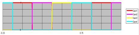
So what we need is a rotating antenna. The problem is that in order to achieve adequate FM deviation with a reasonably compact antenna we need to rotate the antenna somewhere between 15,000 and 120,000 rpm which is nearly impossible so instead we use a circular array of four or eight antennas and use electronics to make the array of antennas look like a single rotating antenna. Thus the use of the term pseudo-Doppler or synthetic Doppler. The simplest way to achieve this rotation is to simply turn one antenna on and then turn the next antenna on while turning the previous one off. A typical switching pattern is shown in Figure 1. Although this technique is the simplest it is not the best because the switching of the antennas takes place when the gain of antenna is at its peak. This generates considerable switching noise that drowns out weak signals.
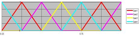
A better approach is our patented smooth summing technique. In smooth summing we gradually increase the gain of one antenna while decreasing the gain of the adjacent antenna. This approach has two main benefits
- A uniform rotating gain pattern is produced providing better accuracy
- Antenna switching occurs when the antenna gain is zero so no switching noise is produced resulting in excellent sensitivity
Figure 2 illustrates the antenna gain pattern on each of the four antennas. A similar pattern is used for the eight element antenna. We at Doppler systems invented this technique and have used it since the early 1990’s in all of our radio direction finders. We’ve found it to perform extremely well giving us excellent sensitivity. As a result our customers can DF signals that are just above the noise floor of their receiver.