Overview
Direction Finder Overview
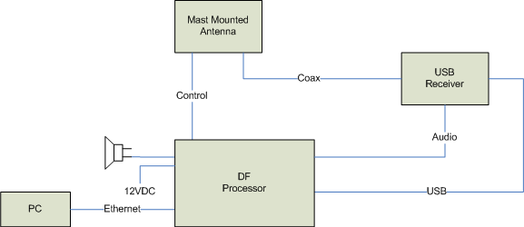
The Doppler radio direction finder (RDF) consist of two main components: the RDF processor and the antenna summing unit. The RDF processor performs the signal processing. The antenna summing unit controls the multi-element antenna array. The system supports many possible arrangements of antennas, processors, receivers, and network configurations. We have illustrated the most basic fixed site arrangement below.

Basic Fixed Site Arrangement
In this configuration, a single processor unit connects to a single antenna and a single receiver. The PC displays bearing data. The PC also controls the radio direction finder and the receiver. The processor provides a host USB port for connection to the receiver, thereby allowing it to be remotely controlled. The RDF processor uses the audio to compute the bearing angle. The audio is filtered to remove the commutation tone and drive the loudspeaker shown. The time-tagged bearing data is sent to the computer via the Ethernet interface.
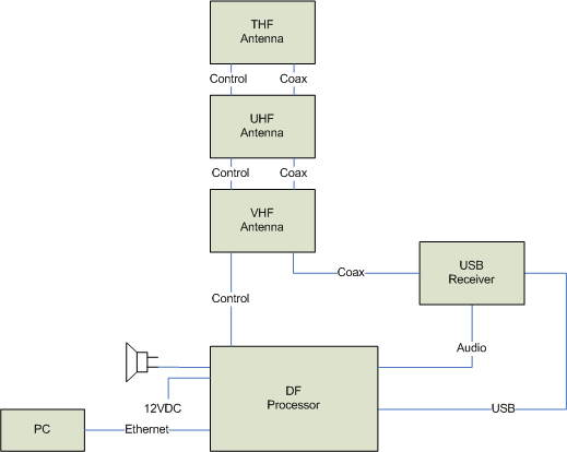
Each fixed site DF antenna has a bandwidth of one octave (115-250, 250-500 and 500-1000 MHz). The antennas themselves accomplish antenna switching. This, therefore, allows one to run a single control cable and a single coax cable to the stacked antenna array. For example, see the diagram below.

Simultaneously DF on Multiple Frequencies
Users can simultaneously monitor multiple channels and compute bearings using the same RDF antenna. Multiple processors connected together accomplish this in a daisy chain arrangement. The Master RDF controls and synchronizes the antenna and the Slave RDF processors. While we show two channels below, the scheme can extend to thirty-two.

Mobile Operation
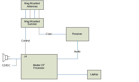
In mobile operation, replace the fixed site antenna with a magnetic mounted RF summing unit and four magnetically mounted quarter-wave vertical antennas. Using the MPT User Interface software, one may construct a simple homing direction finder by simply adding a narrow band FM receiver.

When running an application such as TargetTrack, connect a laptop to the MPT using the Ethernet port. The GPS will connect to the MPT USB port either directly or through a USB-to-serial converter. You may also connect a compass or yaw rate sensor for additional heading readings.
